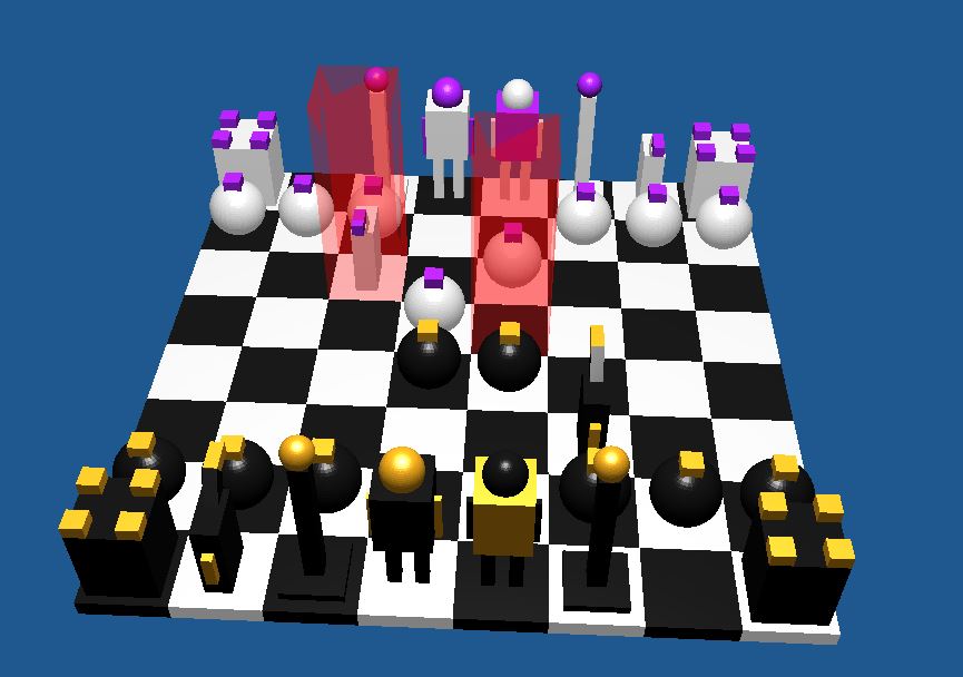
Animated Chess Set
|
This project was created for an introductory rendering class as the final assignment. The assignment was in a "pick-your-own-project" format where you had to demonstrate knowledge of the skills learned in the course. I chose to do an interactive and animated chess game. The major components of this project's implementation were managing user input, hierarchical modeling and animation, handling a variety of different models, and creating a Blinn-Phong shader. The project was created using Microsoft Visual Studio and is written in C++ and GLSL.
Source Code (Drive's notepad works great for veiwing the files) |
Background
- In order to create an environment to accomplish this project I had to compile several external libraries together. GLSL, in order to write the shaders that provided the reflection model, GLFW, a multi-platform library for OpenGL, Eigen, a robust matrix library, and glew, a library that helps OpenGL extension libraries play nice with each other. Additionally the instructor gave us some code to start out with. This code base included a shape class that allowed us to create 3D objects, a main that created a window that would display the shapes, and lastly a MatrixStack class that would create a stack of 4x4 eigen matrices and gave access to important functions such as translate, scale, rotate, and multiply.
- The other piece of code given to us was a Program class which essentially allowed us to create our own customized vertex and fragment shaders. The job of a vertex shader is to apply any desired transformations to a shape, rasterize (map the vertex/normal geometry to pixels) and then pass that information to the fragment shader. The job of a fragment shader is to take the information passed to it (the pixels that correspond to shapes) and decide what color each pixel should be. In order to make this work, the Program class allowed us to send information to each shader in the form of uniform (not rasterized) or attribute (rasterized) variables.
- A simple example of program flow:
- Create a window of some set resolution using GLFW and initialize keyboard and mouse callbacks.
- Initialize GLSL settings, shader programs, and shape classes.
- Loop the render function until the user closes the window
- In render:
- Clear frame buffer
- Initialize perspective, view and model matrices (these allow modification of camera and shape locations and orientations).
- Bind a shader program and set any uniform variables
- Set up the location, scale, and orientation of any desired shapes, and update them as necessary to achieve motion.
- "Draw" each shape. The shape's draw function binds the position, normal, texture coordinate, and element buffers to the currently loaded shader program, allowing the shape to be rendered using the program's vertex and fragment shaders.
- Load the frame buffer to window (now complete with all the information that was just set).
Managing User Input
|
Project Controls
|
Although it had nothing to do with graphics, in order to make the chess game and interactive experience, I had to manage the user's input. As I mentioned above, part of the initialization for the program was the GLFW keyboard and mouse callbacks. A callback is a specifically named function that is called whenever the corresponding action is taken (pressing the mouse button calls the mouse_callback() for example). Then the programmer can design the callback function to handle any input in the desired manner. In my program, the mouse callback does nothing, while the keyboard callback handles all the controls you see on the left.
Essentially the callback is a large if-else block of code, although broken across several functions, that query's what key was pressed and then performs the desired action. Changing the light color was the easiest of the options, as I merely change the value of a global variable which is later sent to shader program. The camera controls work much in the same way from an input perspective. However, to actually change the camera's location or orientation in the window involved changing the camera's identity values. The identity values include a frame separate from the world's XYZ frame, an eye point that specifies exact location in the world, and a look-at point that determines direction. Lastly, to set up the game controls involved setting up the board in a specific location and using simple math to move pieces, and then update the piece's information. The game logic for this program only allowed for the player to move pieces around the board like in reality, it does not check for invalid moves. To accomplish this, I set a up two structures, one for a cell, and one for a piece. The cell structure keeps track of whether the current cell is occupied by a piece, a pointer the piece structure if it is occupied, and its location on the board (0-63). I then made an array of 64 cells, one for each location on the board and updated its information anytime a move was made. The piece structure kept track of its color (material), location, boolean for moving, and a function pointer. I also had two arrays of 16 for each color's pieces, and would update their info as the player made moves. Rather than set up another coordinate system for the board I merely marked the world coordinates of the top left square and the bottom right. At this point I knew the size of a square, so I would change the world coordinates of any moved piece by that size in the corresponding x/y direction. |
HIERARCHICAL modeling and animation
|
Example Matrix Stack:
Tranformation: Top of Stack indentity (I) translate (5 in x, -3 in y, 4 in z) (A) ---------------------------- I rotate (5° to left) (B) push matrix ---------------------------------------------------- AB draw (cube) translate (3 in x) (C) scale (by 1/3) (D) push matrix ------------------------------------------------------ ABCD draw(sphere) pop matrix ------------------------------------------------------ AB draw (cube) pop matrix ------------------------------------------------------- I This will make a cube located at (5, -3, 4), then a scaled down sphere at (8, -3, 4), and finally another cube in the same location as the first. |
Hierarchical modeling is essentially a way to get a model made of multiple shapes to move as either as one, or relative to one another. For example, if you create a model for a human arm and move it up from the shoulder, it would be a pain to have to tell each finger to move up as well. Instead you would rather move the upper arm in any way and just have the rest of the arm follow suit. Hierarchical modeling allows this by setting up a hierarchy (no way!) of each component in a model. To continue the example, the upper arm would be first in the hierarchy, then the lower arm, and then the hand and fingers. Then if you move, twist, or bend the upper arm, the rest of the arm will do the same since it is lower on the hierarchy. Likewise if you transform the fingers, the rest of the arm will not move since it is higher up on the hierarchy.
This is where the matrix stack comes in useful. The way the stack was implemented, was that any new matrix popped on the stack is multiplied by what is currently on top, so any previous transformation is preserved. The (attempted) diagram on the left shows how a example of this system works. The biggest design problem I faced in the program was how to animate each piece separately and yet control them all the same. My solution was to have the piece structure hold a function pointer to a specific function that defined how to draw and animate each respective piece, and a boolean for moving. Then in each function, I would draw the hierarchically modeled piece, and if the moving boolean was set, create some simple animation for it to do while changing spots on the board. |
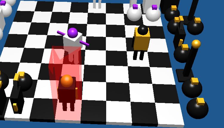
Rendering process and shaders
As mentioned earlier, the Program class allowed me to create my own customized vertex and fragment shaders. For this project, I created two shader programs, one to control the color of the chessboard and pieces, and another to create the translucent red block that serves as the cell highlighter. The highlighter program was very simple, with the vertex shader just passing the vertex info through the rasterizer, and the fragment shader just setting all pixels to a translucent red. The other shader program was slightly more complex. The vertex shader calculated the the vector from the current vertex to the light, the view vector, and the normal to the vertex and passes this information for us in the fragment shader. The fragment shader computes the Blinn-Phong color for each pixel by computing the diffuse and specular components using the information sent from the vertex shader. Also the Blinn-Phong shader program has a uniform variable that represents the material color of the object, which is set for each shape before that shape is sent to the shader program.